I have recently been working on tuning circuits, which typically consist of an inductor and a capacitor (i.e. an LC circuit). For those not familiar with inductors, they are passive components that store energy in a magnetic field. They oppose changes in current, meaning that they pass direct current (DC) and block alternating current (AC).
While there are many types of inductors, ferrite core inductors are useful because the high magnetic permeability of ferrite leads to a significant increase in induction. One common use case for ferrite core inductors is ferrite loopstick antennas in AM radios, where the inductor acts as both an antenna that interacts with the magnetic component of the carrier wave, and a component of the tuning circuit. Even the earliest transistor AM radios, such as the Regency TR-1 and Sony TR-55, used ferrite loopstick antennas.
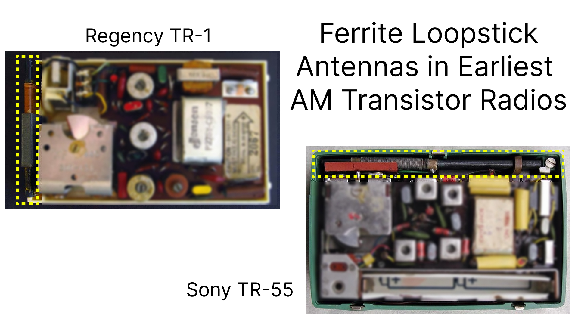
(original Sony TR-55 internals image from u/1Davide on Reddit, original Regency TR-1 internals image from Nuts & Volts)
While inductors can be difficult to work with, they are fairly easy to make with basic supplies. Doing so allows you to manipulate the design of the inductor to fit the necessary attributes for your application.
An Air Core Inductor Link to heading
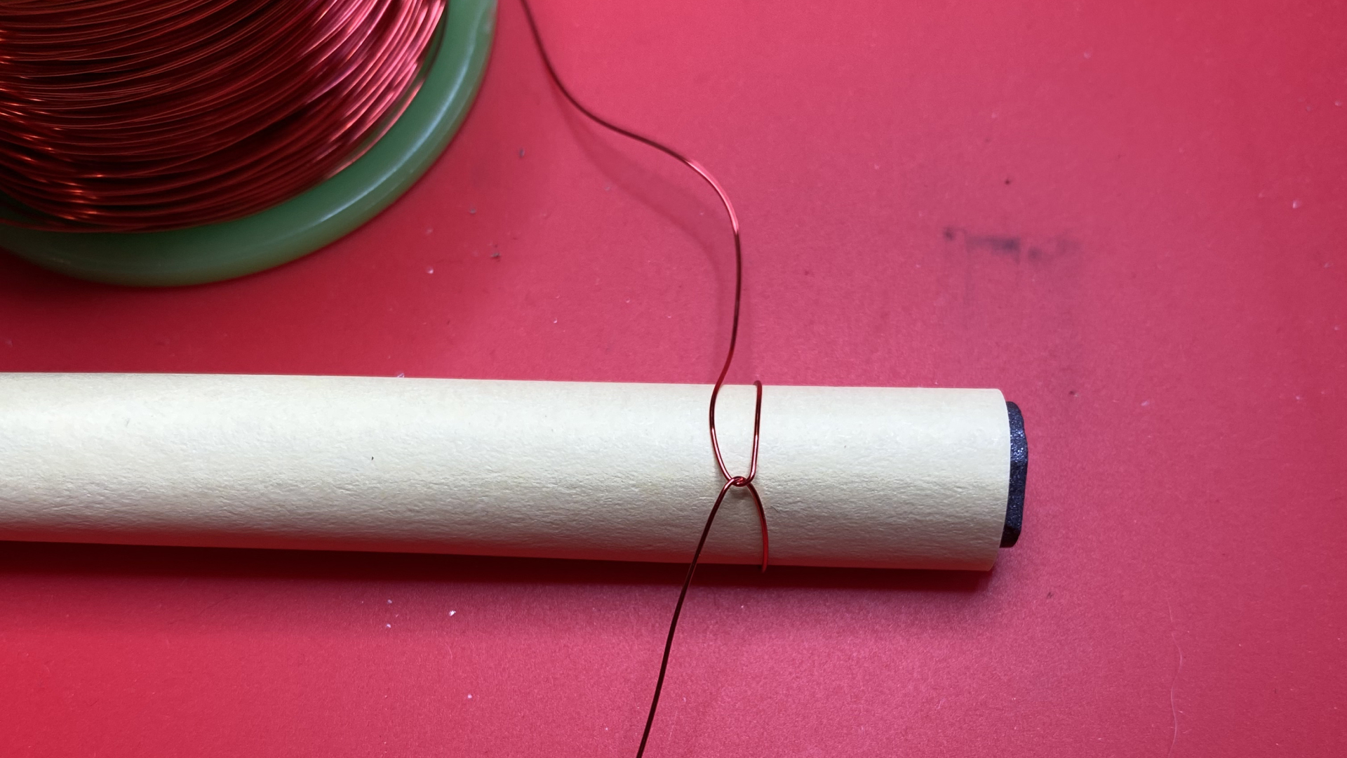
In order to observe ferrite’s impact on inductance, we can start by creating an inductor consisting of only a wire coil, or an “air core”. To make it easier to reuse in the future, we can create the coil by wrapping it around a ferrite rod, then slide it off. I typically will use a piece of paper (such as a sticky note) to make it easier to remove the coil, or move it to a different position on the core material.
We’ll start, somewhat arbitrarily, with 30 turns of 28 AWG magnet wire around the core. Starting by creating a small loop and feeding one end of the wire through it helps to keep the coil from unraveling.
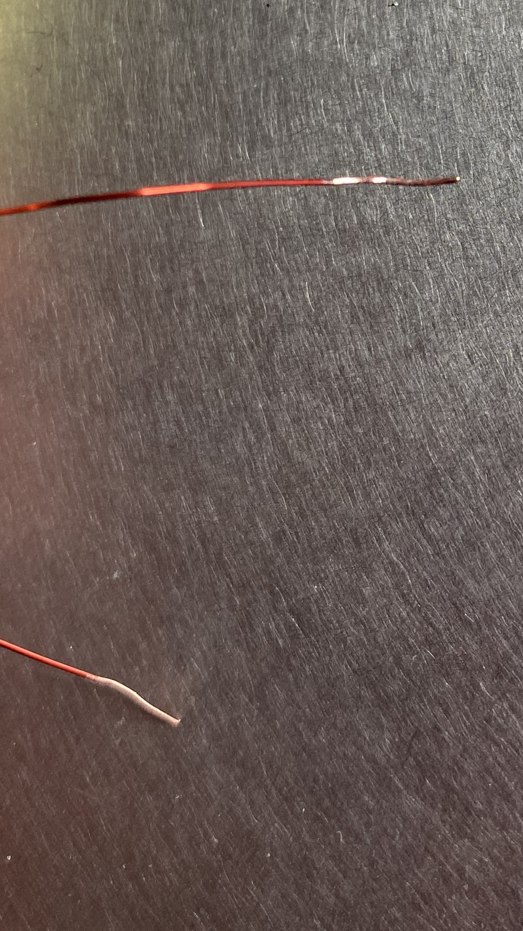
We can also use tape to secure the core to the paper to keep it intact as we move and test it. There are a variety of strategies that can be leveraged to measure inductance, but we’ll use an LCR (inductance, capacitance, resistance) meter for convenience. I have the DE-5000, which is an affordable, decent quality option. Because the magnet wire is enameled, we need to strip the ends before we can measure with the LCR meter. A box cutter, craft knife, or sandpaper can be used. You should be able to see the exposed copper at the ends after the enamel is removed.
After stripping, the LCR meter alligator clips attachment can be used to clamp onto each of the ends of the coil.
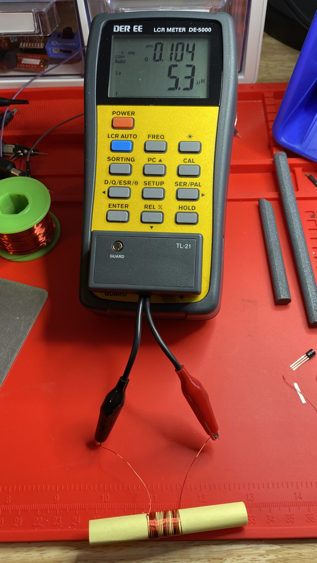
As expected, the measured inductance is quite low (5.3 uH).
Adding a Ferrite Rod Link to heading
As previously mentioned, wrapping the coil around a ferrite core increases the
inductance. I ordered a set of ferrite rods, which
arrived with some intact and some broken into smaller pieces. We can start with
one of the broken rods so that we can see the impact of increasing the length
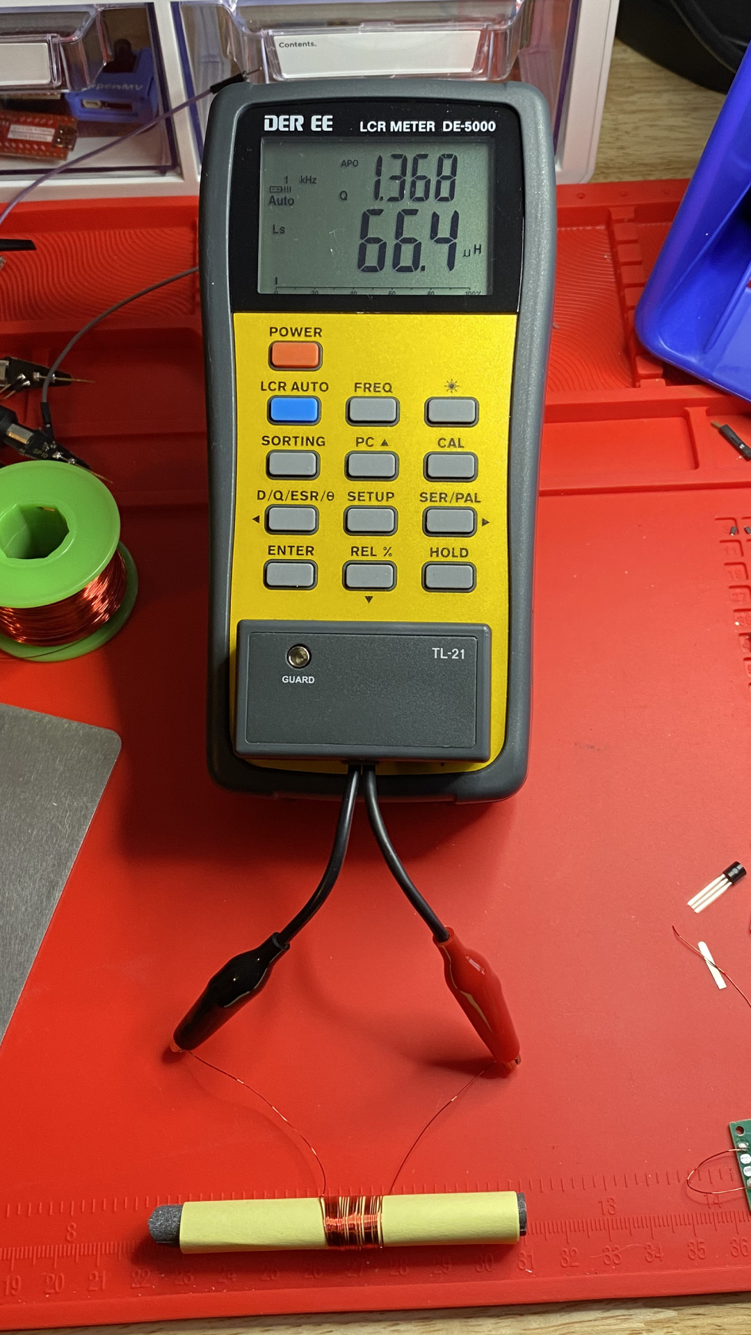
later. This shorter rod is ~85 mm.
Since we used the ferrite rod to wrap the coil, we can easily slide it back on.
As expected, we see an inductance reading of 66.4 uH, an order of magnitude
larger than that of the air coil.
Using a Longer Ferrite Rod Link to heading
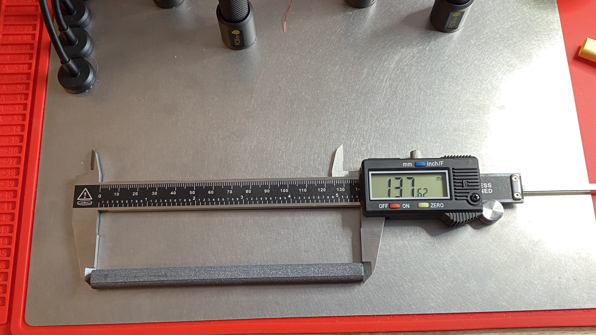
The untainted rod is 137 mm, about 60% longer than the broken rod we
previously tested.
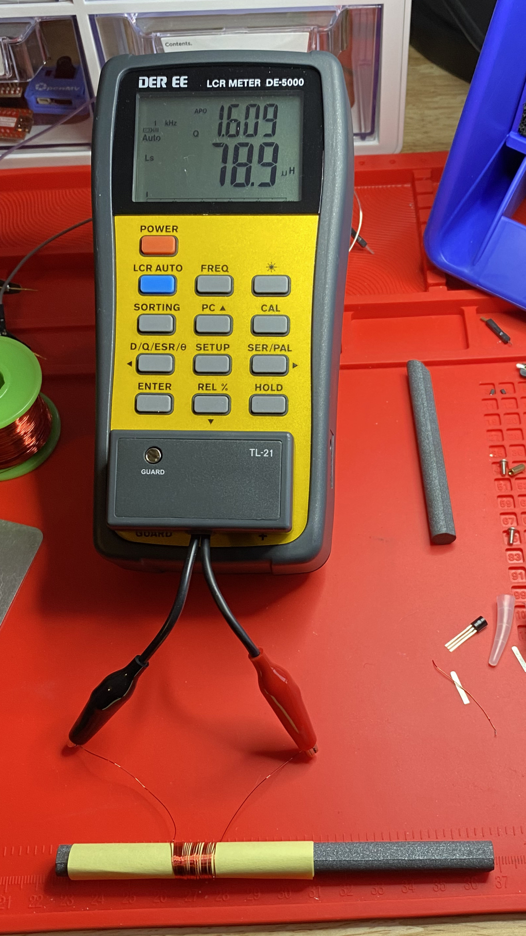
Simply moving our coil to one of these longer rods increases the inductance from
66.4 uH to 78.9 uH.
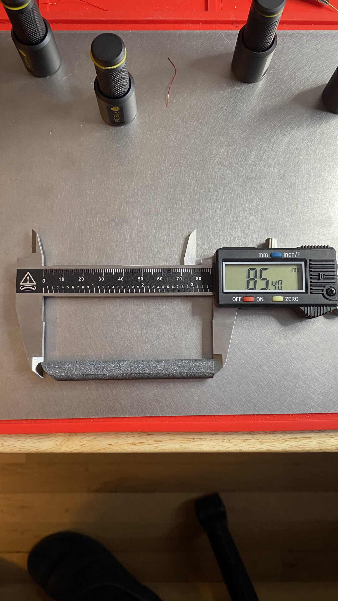
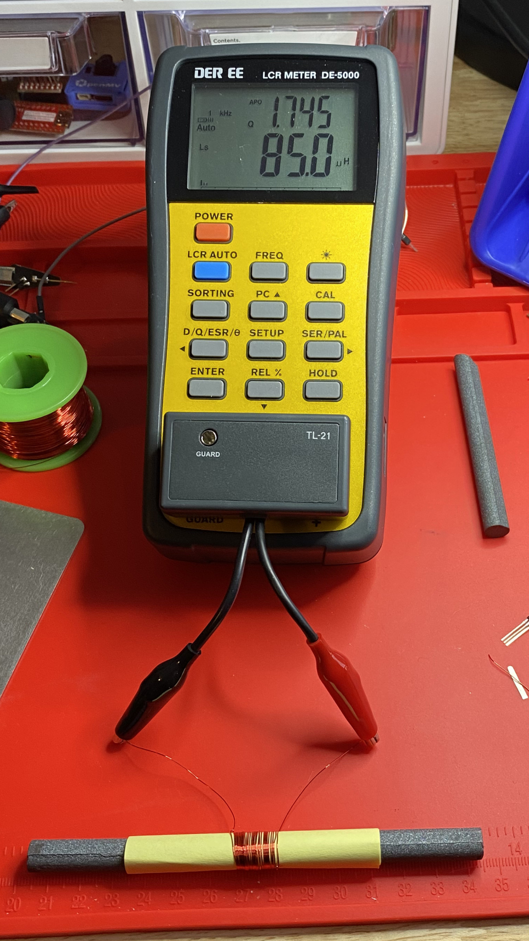
Moving Position on the Ferrite Rod Link to heading
Another thing we can do to change the inductance is changing the position on the
ferrite rod. You may have noticed that when testing the longer ferrite rod, the
coil was positioned close to one end. The closer the coil is to the center of
the rod, the greater the inductance. Compared to moving from an air core to a
ferrite core, the change is minimal (78.9 uH to 85.0 uH). However, sliding
the coil along the rod is much easier than adding or replacing an existing rod
in a circuit, making it a useful strategy for small adjustments.
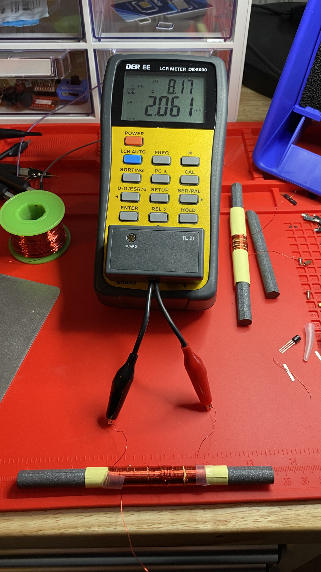
Increasing the Length of the Coil Link to heading
We can also increase the inductance by increasing the length of the coil, while
maintaining the same density. This has a much larger impact on inductance, but
either involves winding a new coil, or splicing a wire to one end of an existing
coil. In measuring a coil I previously wound with 150 turns, we can see the
inductance increases to 2.061 mH, or 2,061 uH.
Optionality with Taps Link to heading
Increasing the number of turns is a fairly involved change to make. It would be easier if you could easily test and move from one level of inductance to another. One way to do so is by installing “taps” in the coil. There are a number of ways that you can go about installing taps.
- While winding the coil, cut it every X turns, then wind it together with a new strand of wire, then continue winding. With this strategy, the tap wires are pre-installed in the event that you need to use them.
- Create small loops every X turns as you are winding the coil. When a tap is needed at one of the loops, remove the enamel from the loop and from a short strand of wire, then attach the short strand of wire to the loop by passing it through and twisting it back around itself. This is a non-destructive strategy that avoids adding unnecessary taps, while making it easy to add new ones as needed.
- Wind the coil to the maximum desired length, then remove the enamel from the desired tap location and solder a short wire to the location. This takes more effort, but can be done to any existing inductor coil.
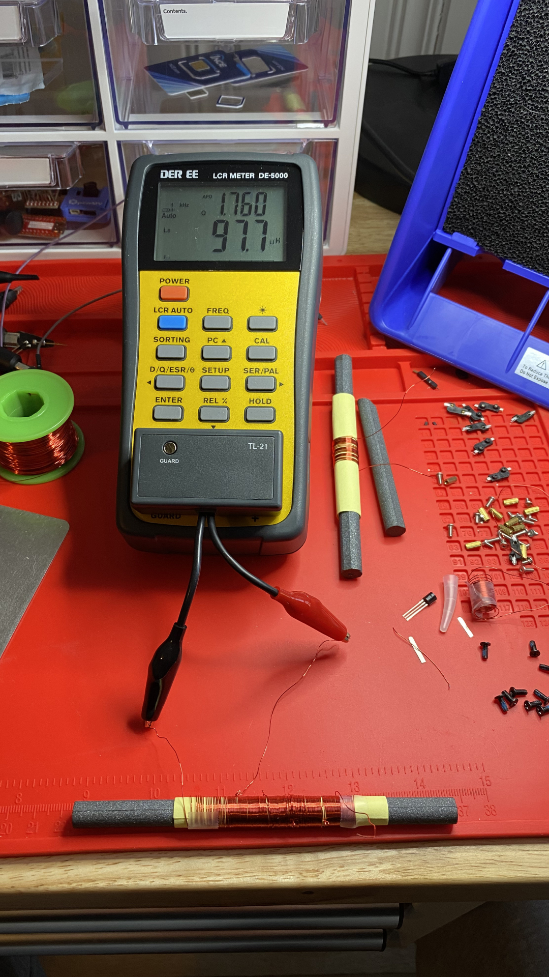
In the previous image, you may have noticed another wire protruding from the
coil ~1/5th the total length (~30 turns) from the start of the coil. On this
long coil, I installed taps every ~30 turns, then attached a wire at the first
tap. While not exact, we can see that the measured inductance at this tap (97.7 uH) is fairly close to the shorter coil we measured at the center of a ferrite
rod of similar length (85.0 uH).
Another use case for taps is to effectively divide the coil into two inductors, with inductive coupling allowing passing of a signal from one to the other. This is common in AM radios, such as those mentioned at the beginning of this post.
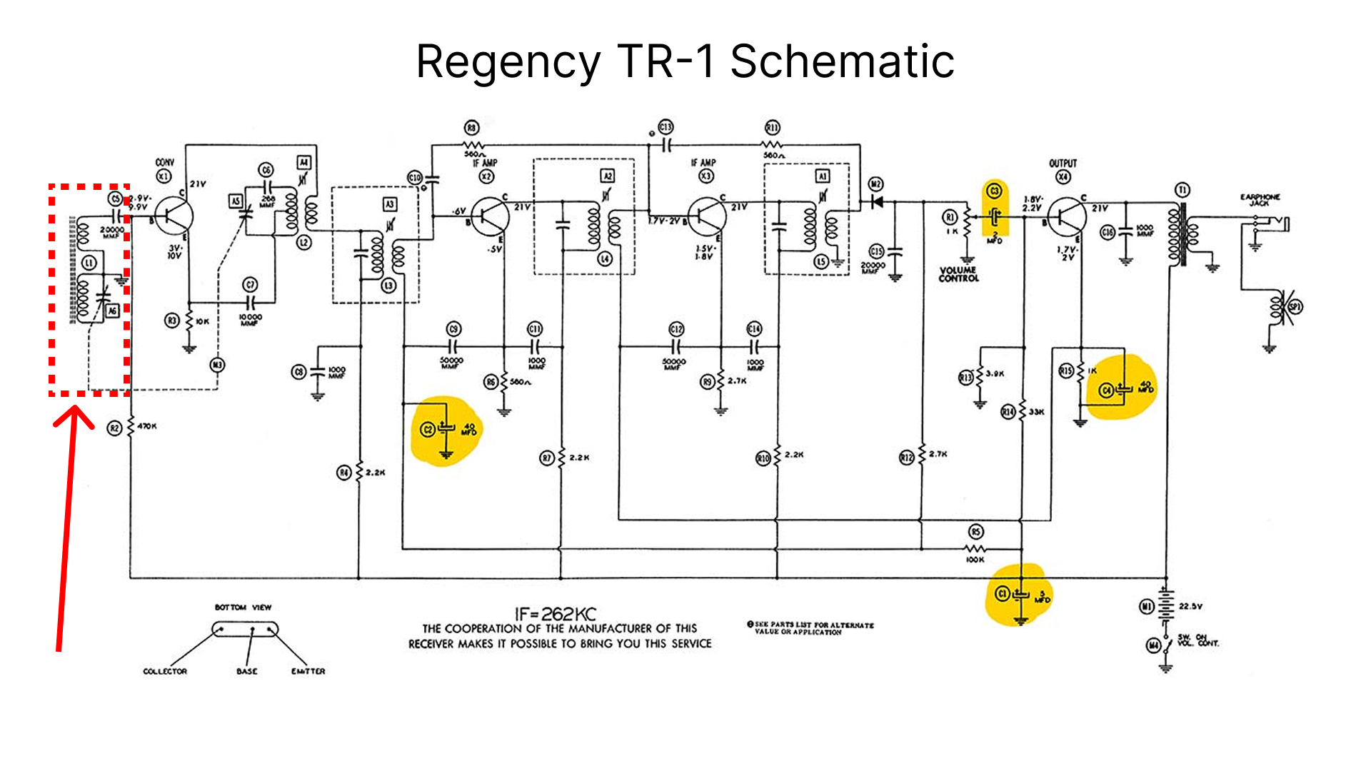
(original TR-1 schematic image from Nuts & Volts)
Separating the tuning circuit from the rest of the radio’s amplification and filtering stages helps avoid negatively impacting the sensitivity of the tuning circuit (i.e. its Q factor) due to loading, while also reducing the potential for parasitic oscillation. This can be accomplished via a tap, or by two completely separate coils, potentially sharing the same core.
Other Strategies Link to heading
There are many more strategies in addition to those explored in this post. For example, the type of wire, the guage of the wire, and the diameter of the coil can also all be modified to alter inductance. While it is possible to calculate the inductance of a solenoid, and doing so is certainly directionally useful, variations in materials make constructing and measuring necessary.