This is part of a series on the blog where we explore RISC-V by breaking down real programs and explaining how they work. You can view all posts in this series on the RISC-V Bytes page.
So far in this series, we have been looking at the assembly generated when compiling relatively simple programs. At this point, we have seen instructions that perform a wide variety of operations. Let’s take another look at our minimal example from the Passing on the Stack post:
minimal.c
#include <stdio.h>

int sum(int one, int two) {
    return one + two;
}

int main() {
    printf("The sum is: %d\n", sum(1, 2));
    return 0;
}
riscv64-unknown-elf-gcc -O3 -fno-inline -march=rv64g minimal.c
Hold up a minute, what is that
-march=rv64gdoing in there? We didn’t compile with that flag in the last post, but we are providing it here to disable instruction compression. The defaultmarchfor our toolchain isrv64gc(or more specificallyrv64imafdc), but we are removing theCextension, which indicates that a machine supports instruction compression. In a future post we will explore how compression improves code size and why it makes our generated assembly look different. You may already notice some changes in the output below!
(gdb) disass main
Dump of assembler code for function main:
   0x00000000000100b0 <+0>:         addi        sp,sp,-16
   0x00000000000100b4 <+4>:         li          a1,2
   0x00000000000100b8 <+8>:         li          a0,1
   0x00000000000100bc <+12>:        sd          ra,8(sp)
   0x00000000000100c0 <+16>:        jal         ra,0x101b8 <sum>
   0x00000000000100c4 <+20>:        mv          a1,a0
   0x00000000000100c8 <+24>:        lui         a0,0x21
   0x00000000000100cc <+28>:        addi        a0,a0,-192 # 0x20f40
   0x00000000000100d0 <+32>:        jal         ra,0x10418 <printf>
   0x00000000000100d4 <+36>:        ld          ra,8(sp)
   0x00000000000100d8 <+40>:        li          a0,0
   0x00000000000100dc <+44>:        addi        sp,sp,16
   0x00000000000100e0 <+48>:        ret
End of assembler dump.
(gdb) disass sum
Dump of assembler code for function sum:
   0x00000000000101b8 <+0>:         addw        a0,a0,a1
   0x00000000000101bc <+4>:         ret
End of assembler dump.
In just this small example, we see multiple different types of instructions, and their operands do not all look the same. Let’s take a look at a few of them:
addi: we are using this in three different places in<main>to add or subtract a value from one register and store it in another.
<+0>:      addi        sp,sp,-16         # increase size of the stack frame by subtracting 16 bytes from stack pointer
...
<+28>:     addi        a0,a0,-192        # add -192 (base 10) to the value currently in a0
...
<+44>:     addi        sp,sp,16          # move stack pointer back to its location when we began the procedure
sd: we are using this in<main>to store the caller-saved return address (ra) to a memory location on the stack.
<+12>: sd ra,8(sp)
lui: we are using this in<main>to do . . . something?
Don’t worry, we are going to define “something” in a bit.
<+14>: lui a0,0x21
addw: we are using this in<sum>to add the values ina0anda1and store the result ina0.
<+0>: addw a0,a0,a1
There are more instructions than these four, but you’ll notice something
interesting about this group: all of them take operands in a slightly different
manner. For instance, addi takes three operands, two of which are registers,
and one of which is a decimal value (base 10). sd takes two operands, one
register and one register with an offset (more on this in a bit). lui takes
two operands as well, the first being a register, and the second being a
hexadecimal value (base 16). Lastly, addw takes three operands, all of them
registers.
Why is this interesting? Well, though we often think about assembly as “talking directly to the hardware”, it is important to remember that the processor understands binary machine code. Therefore, each of these instructions, as well as all of their operands, must be encoded in binary in order to be interpreted. When different operations require varying numbers and types of operands, we must tell the processor how to interpret the operands that we provide.
RISC-V Instruction Format Overview Link to heading
The binary encoding of an operation is referred to as its instruction format. RISC-V has six core instruction formats:
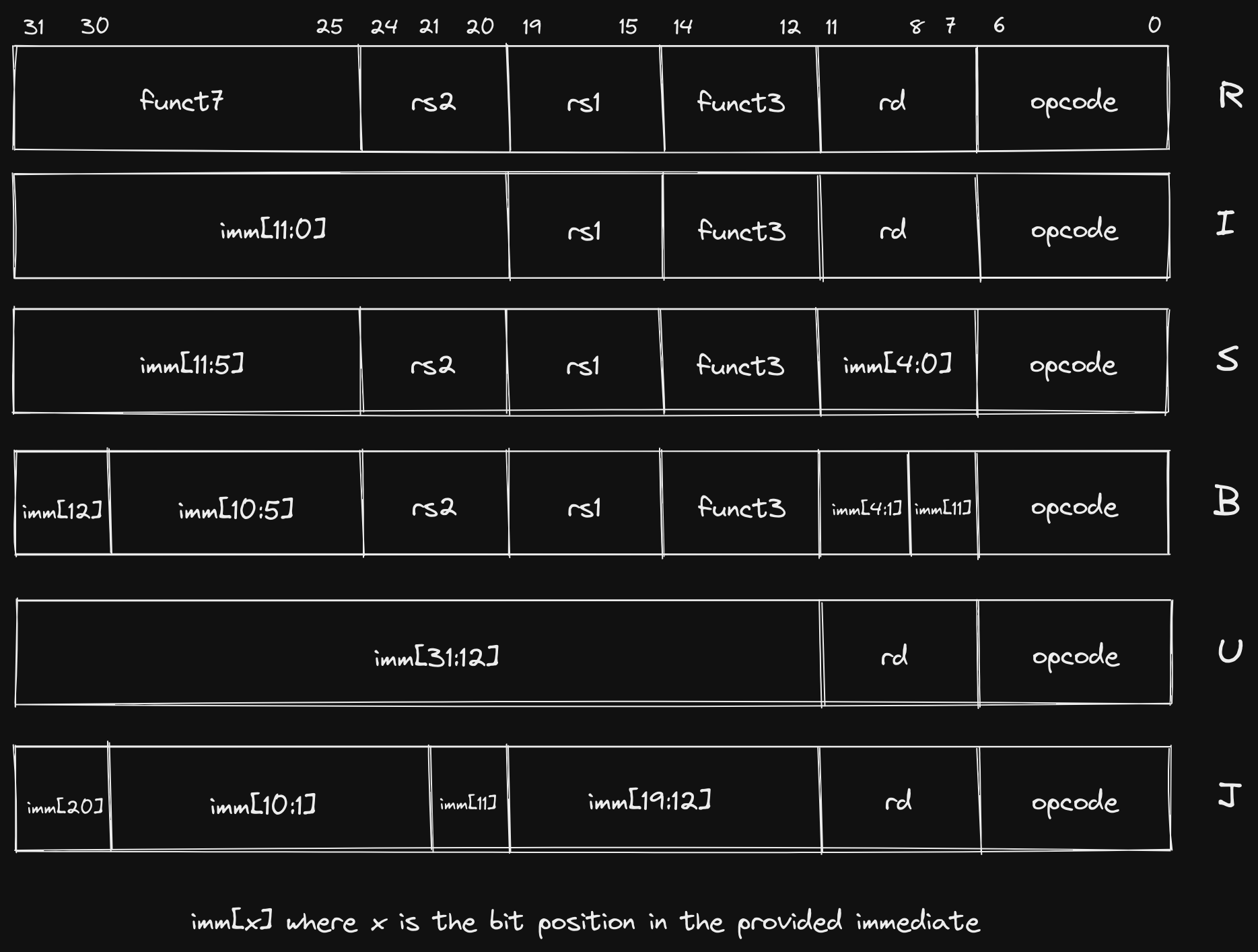
The
Bformat is variation ofSand is sometimes referred to asSB. Similarly, theJformat is a variation ofUand is sometimes referred to asUJ.
There are a few immediate observations we can make about these core formats:
- They are all 32 bits (
[31:0]) wide. - They all reserve the first 7 bits (
[6:0]) for theopcode. - If two formats support the same operand, that operand is always in the same
location in the instruction (e.g.
R,I,S, andBformats all have anrs1operand and it is always encoded in bits[19:15]). - Each involves at least one register operand (
rd/rs1/rs2). - All register operands are the same number of bits (5).
Each format is designed to accommodate certain types of instructions. While two types of instructions that fall under the same format may seem unrelated, we will see later on that they frequently will be implemented using the same underlying operations in the Arithmetic Logic Unit (ALU).
R: register-register ALU instructions (jump to section)I: ALU immediate instructions, load instructions (jump to section)S/B: store instructions, comparison and branch instructions (jump to section)U/J: jump instructions, jump and link instructions (jump to section)
Each of the instructions we saw in our generated assembly adheres to one of these formats. The four instructions we specifically identified map as follows:
addi: I Formatsd: S Formatlui: U Formataddw: R Format
Let’s take a look at each of these formats and explore why they are appropriate for different instruction types.
Why Multiple Formats? Link to heading
We already answered this abstractly by saying that we need to encode operations in binary for the processor to understand them. However, what does that mean concretely? At its most basic level a CPU is a set of logic gates that are composed together to offer higher-level abstractions (such as the instructions we write in assembly). In order to know what signals to pass to the various modules that perform data operations, the CPU must know what we are asking it to do.
A Metaphor for Humans Link to heading
This brief section attempts to draw parallels to how two humans might communicate. If you are already familiar with how instructions are represented on a machine, or you just don’t like metaphors (which, quite frankly, typically describes me), you may want to skip ahead.
Imagine you were coordinating a time-sensitive event with a friend, but all communication had to happen via individual messages with length of 30 alphanumeric characters or less. Further imagine that you could only send one message per hour. One option would be to explain everything you needed them to do explicitly, writing in common prose. For example, if you wanted them to go buy some food for the event, you could say “Go to the store on Main Street”, then an hour later say “Buy seven wheat hamburger buns”. However, if the store was only 5 minutes away, our friend would have to wait for 55 minutes until they got the subsequent message telling them what to do at the store.
A more efficient strategy, assuming prior planning was permitted, would be to
agree upon a set of tasks that our friend was capable of doing and a way to
encode those tasks as characters other then the very inefficient English
encoding we just demonstrated. When we say “Go to the store on Main Street” we
are really just providing an action (“Go to”), a recipient of that action
(“store”), and a modifier of the recipient (“on Main Street”), each of which
could be specified with a single character or a small group of characters,
instead of the 30 characters we are using. However, our friend needs to know how
many characters are dedicated to defining each segment of the task in order to
distinguish where one ends and the next begins. The decision on how many
characters are required to represent each comes down to how many different
variations we need. With alphanumeric characters (A-Z, 0-9, case-insensitive),
we can describe 36 variations in a single character. If our friend is capable of
36 or less actions, the most efficient way to communicate the action to them is
with a single character. On the other hand, let’s say there are more than 36
action recipients that we need to encode. By using two characters, we are
suddenly able to encode 1296 action recipients (36^2 = 1296)! So at this
point, we are able to represent in 3 characters (1 for the action, 2 for the
recipient) what we were previously representing in 15 (“Go to the store”).
For the last part of the instruction, there are many ways that we could describe
the store, so we may need a few characters. In our English example, we only had
enough characters to communicate the street name of the store. If we can
communicate its location in a more efficient format, we could be much more
specific. For completeness, let’s say the remaining 27 characters are used to
encode the location of the store (giving us 36^27 options!). We can now
communicate the full street address to our friend, demonstrating the ability to
represent more information when a format for communicating that information is
predefined.
However, when we look at our next instruction, “Buy seven wheat hamburger buns”, we notice a problem. We now have an action (“Buy”) and a recipient (“hamburger buns”), but two (“seven” and “wheat”) recipient modifiers. Attempting to encode this task in the same format as we did for going to the store will result in confusion for our friend as they try to decipher the encoding of “seven” and “wheat” into a location (i.e. street address) of the hamburger buns they are buying. We have now identified two separate classes of tasks, and they require different information to be presented in their encoding. Our “Buy” action would prefer to split those characters we used to describe the location of the store in the first task into multiple modifiers of the object being bought.
How can we accommodate both of these (and potentially more) classes of tasks? One manner of doing so would be to dedicate one or a few characters at the beginning of our message to describing how the remainder of the task is going to be formatted. For instance, if we reserve the first character for describing the class of task, our friend can know that if the first character is “A”, the remainder of the message will contain an action, a recipient, and a single long modifier. If the first character is “B”, the message will contain an action, a recipient, and two shorter modifiers.
Back to Computers Link to heading
Similar to our strategy of encoding the type of task we are communicating to our
friend with a single character, RISC-V defines the class of task (instruction
format) using a fixed-length opcode in the 7 least significant bits of every
instruction.
Importantly, though the
opcodedoes encode the instruction format, it is also used to indicate other information about the specific instruction. For this reason, twoRformat instructions, for instance, may not have the same 7 bitopcode. However, because theopcodeeventually gets transformed into control signals, you will see at least similar, if not identical,opcodesfor instructions of the same format.
It can be helpful to think about each instruction format as making a different
tradeoff between how it utilizes the 25 remaining bits it is allocated. Some
instructions may only need to use general purpose registers as operands, and
since there are only 32 general purpose registers, they can all be addressed
with just 5 bits (2^5 = 31). This leaves room for more instruction types in
that format by utilizing the remaining bits to encode the operation (we’ll see
an example of this with the funct3 and funct7 fields in R format
instructions). Other instructions may only need a single register operand, but
require the ability to pass a large constant value (U format instructions are
a good example of this).
The following sections describe how each instruction format caters to different types of operations we want to perform.
R Format Link to heading
R format instructions are frequently thought of as the most “simple” because
they typically include operations that map closely to the capabilities that we
generally associate with a computer at the lowest level. Arithmetic operations,
such as adding, subtracting, and bit shifting all fall into this category.
We picked out addw as an instruction from our example that adheres to the R
format. Let’s take a look at the 4 bytes at that address in binary:
(gdb) x/4bt  0x101b8
0x101b8 <sum>:      00111011    00000101    10110101    00000000
RISC-V is a little endian
architecture, meaning that the least
significant byte is stored at the smallest memory address. If we take the 4
bytes at 0x101b8, which is the location of our addw instruction, we can
re-arrange the bytes so that the least significant bit (LSB) is on the right and
the most significant bit (MSB) is on the left:
00000000 10110101 00000101 00111011
Now we can fit this into the R format we defined earlier:
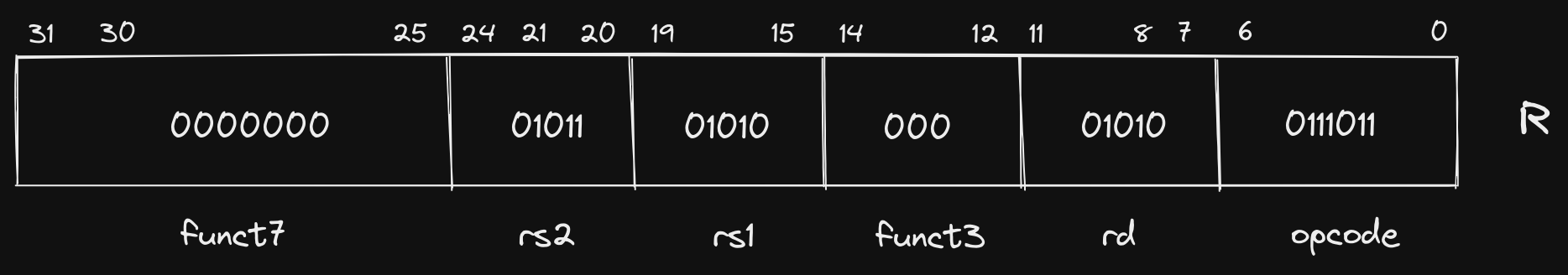
Let’s break down the components of this instruction. As is true for all of our
core formats, the first 7 bits ([6:0]) represent our opcode. Here our opcode
is 0111011. This informs the CPU what format, and, depending on the
instruction, the exact operation that needs to be performed on the operands. In
cases where the opcode does not correspond to a single instruction, it informs
the CPU where to look for more information. In R format instructions, both
funct3 and funct7 fields are supported, and they are used to specify the
exact instruction that should be executed. We will dive into exactly how the
opcode is decoded and transformed into control signals in a future post, but
as an example of how the opcode and funct fields are used to specify an
instruction, we can compare the three fields for addw and subw:
| Instruction | opcode | funct3 | funct7 |
|---|---|---|---|
addw |
0111011 |
000 |
0000000 |
subw |
0111011 |
000 |
0100000 |
As observed, the only difference is a single bit in the funct7 field, but this
is enough to inform the CPU of how to operate on rs1, rs2, and rd. This is
an example of a format allowing for more types of instructions to be defined
because the size of the operands are small (5 bits each).
Speaking of the operands, we haven’t examined the values of rs1, rs2, and
rd yet. The first thing you will notice is that rs1 and rsd contain the
exact same bit sequence: 01010. This should come as no surprise if we look
back our instruction, which uses a0 twice: addw a0,a0,a1. How does this
sequence of bits correspond to a0 though? If you remember our table of general
purpose registers (GPRs) from earlier posts, you’ll recognize a0 as the
mnemonic for the first “argument register”. A truncated version of the table is
reproduced below as a refresher:
| Name | ABI Mnemonic | Calling Convention | Preserved across calls? |
|---|---|---|---|
| x10-x17 | a0-a7 | Argument registers | No |
We can see that a0 corresponds to GPR x10, and if we convert our rs1 and
rd values (01010) to decimal, we see the value is 10!
Quick refresher on converting binary to decimal:
0(1) + 1(2) + 0(4) + 1(8) + 0(16) = 10.
Likewise, the value of rs2 (01011) is 11 when converted to decimal,
corresponding to x11.
I Format Link to heading
I format instructions eliminate the second register (rs2) and function
(funct7) fields from the R format in favor of a large immediate value
field. This format is specifically useful for supplying constants for arithmetic
instructions, or loading data from a location in memory. We’ll take a look at
both of those here.
The instruction we chose as representing I format instructions from our
example was addi (“add immediate”). We’ll examine the first instance of the
instruction, which is used to increase the size of the stack by decrementing the
stack pointer sp:
(gdb) x/4bt 0x100b0
0x100b0 <main>: 00010011    00000001    00000001    11111111
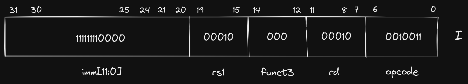
Rearranging the bits and fitting into the I format gives us the following:
11111111 00000001 00000001 00010011
Let’s again look at a truncated table of RISC-V GPRs:
| Name | ABI Mnemonic | Calling Convention | Preserved across calls? |
|---|---|---|---|
| x2 | sp | Stack pointer | Yes |
Unsurprisingly again, our rd and rs1 fields are identical, both
corresponding to the stack pointer register sp (00010 is 2 in decimal,
sp is register x2). Our immediate value (111111110000) looks a little
strange though. Our instruction specified addi sp,sp,-16, but if we convert
111111110000 to decimal we get 4080?
We have demonstrated multiple times at this point how decimal numbers can be
represented in binary, but what if we need to represent a negative number, as we
do here? RISC-V, and almost every other modern machine, uses Two’s
Complement. We will go into
more depth in a future post about why Two’s Complement is friendly to hardware
designers, but for the purposes of this post, we can make the simple observation
that any binary number with a 1 in the most significant bit position
(imm[11] in this case), is negative, and its decimal value can be ascertained
by inverting all bits, converting to decimal, and adding 1. Let’s do that here:
# Invert bits
111111110000 => 000000001111

# Convert to decimal
000000001111 = 1(1) + 1(2) + 1(4) + 1(8) = 15

# Add 1
15 + 1 = 16

# Add sign
-16
In summation, our instruction has specified that -16 be added to the value in
the sp register, and the result be stored in the sp register, effectively
increasing the size of our downward growing stack.
Before we move on to the next instruction format, let’s look at another I
format instruction from our example that looks fairly different than addi:
0x00000000000100d4 <+36>: ld ra,8(sp)
Here we are loading the contents of the memory location 8 bytes greater than the
location stored in sp and storing it in the return address register (ra).
The 8 in this instruction is frequently referred to as an offset. Let’s look
at the binary representation:
The
dinldstands for “doubleword” which indicates the size of the data at the memory location is 64 bits.
(gdb) x/4bt 0x100d4
0x100d4 <main+36>:  10000011    00110000    10000001    00000000
Rearranged: 00000000 10000001 00110000 10000011
Fit into I format:
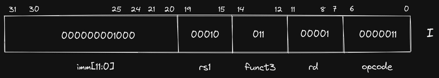
The first thing you’ll notice is that the opcode is different (though only by
a single bit), and we are using the funct3 field to further describe how the
other fields should be interpreted. The rest of the instruction is similar to to
the others we have seen, rd corresponds to ra (x1), rs1 corresponds to
sp (x2), and our immediate value represents our 8 byte offset. The
differences in these two instructions (addi and ld) demonstrate how a single
instruction format can be useful for multiple types of instructions, and we can
indicate to the CPU how fields should be interpreted using our opcode and
funct fields.
S Format Link to heading
Next up is S format instructions, which reintroduce our second register
operand (rs2), but eliminate the destination register rd. An important
attribute to notice is that we don’t simply change the bits used for rd to now
represent rs2, we instead split our immediate value across two separate
fields, allowing rs2 to be placed in the same location in S format
instructions as it was in R format (and every other format that utilizes
rs2). When we explore how instruction decoding works, the reasoning behind
this strategy and the impact it has on complexity of the hardware design will
become more apparent.
Our chosen S format instruction is sd which is used to store a doubleword at
a location in memory:
(gdb) x/4bt 0x100bc
0x100bc <main+12>:  00100011    00110100    00010001    00000000
Rearranged: 00000000 00010001 00110100 00100011
Fit into S format:
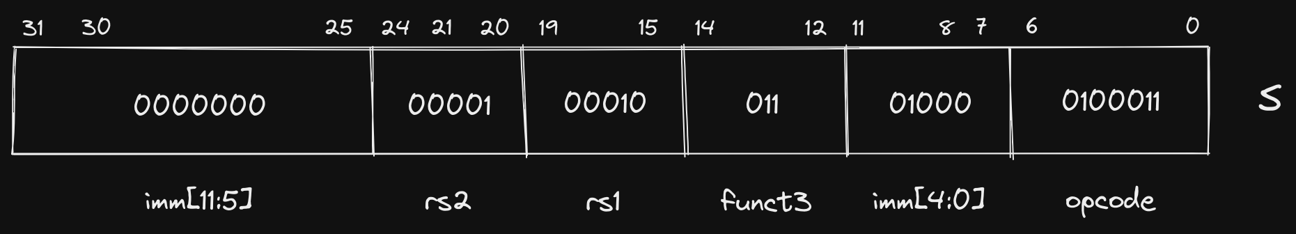
This looks somewhat similar to our ld instruction, but instead of storing the
contents of a memory location in a register, we are storing the contents of a
register in a memory location. In this case, the contents of ra are being
stored at the memory location specified by the sum of the contents of our sp
register and 8, which is the decimal value of our immediate: 000000001000.
The practice of deriving a memory address by taking the sum of a register’s contents and an immediate offset is commonly referred to as base or displacement addressing.
As mentioned earlier, the B format is often grouped with S because it is
only slightly different. The difference is rooted in the fact that the B
format is typically used for conditional branching instructions, where the
immediate value is used to specify the memory location where execution should
continue if the comparison evaluates to true. If you remember the beginning of
this post, we mentioned that all instructions in RISC-V are 32 bits wide (or 16
bits wide if using compressed instructions). As a consequence, we will only ever
be branching to a memory location that is a multiple of 2. Therefore, specifying
the least significant bit in our immediate value would be a waste of space (it
will always be a 0). Instead, we use the 8th bit in the instruction to
represent the 12th bit in our immediate value (imm[11]). In doing so, we are
able to re-use much of the hardware utilized for evaluating S format
instructions because the sign bit of the immediate value (imm[12]) is in the
same location, as are the middle bits of the immediate value (imm[10:1]). We
are also able to specify larger immediate values because we have 13 bits instead
of just 12.
Though we don’t have any B format instructions in our example program, let’s
take a look at how we could decode a blt instruction if it existed:
0x00000000000101b8 <+0>: blt a1,a0,0x101c4 <sum+12>
(gdb) x/4bt 0x101b8
0x101b8 <sum>:  01100011    11000110    10100101    00000000
Rearranged: 00000000 10100101 11000110 01100011
Fit into B format:
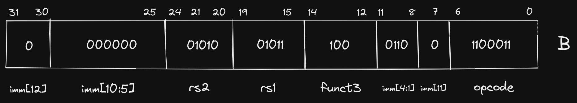
Since we’ve seen it a few times at this point, I’ll leave the register decoding
to you, but let’s briefly evaluate our immediate. Remember that we infer a 0
in the least significant bit (imm[0]):
0000000001100
In practice, immediate values are sign-extended, but we represent them without sign-extension in this post to more clearly show the mapping of bits in the instruction to bits in the immediate.
Converting to decimal, we get a value of 12, which, as we can see from our
assembler directive above, is the number of bytes (i.e. offset) between the
current instruction memory address (0x101b8) and 0x101c4.
U Format Link to heading
Our last instruction format is U, which we chose the lui instruction to
demonstrate, but didn’t specify its actual purpose. lui refers to “load upper
immediate”, and now that we have looked at a few instructions that use immediate
values, we should have somewhat of an intuition for how it is used. The U
format has the smallest number of fields out of all core instruction formats,
only supporting opcode, rd, and a 20 bit immediate.
We have already seen control flow instructions in the SB format with
conditional branching, but we did not observe the limitations. Because the size
of our immediate in SB instructions was limited to 13 bits, the total memory
address space that could be accessed in a single jump is limited. For this
reason, conditional branching is frequently used for small, local jumps.
Before we go farther, let’s break our lui instruction down into its U format
layout:
(gdb) x/4bt 0x100c8
0x100c8 <main+24>:  00110111    00010101    00000010    00000000
Rearranged: 00000000 00000010 00010101 00110111
Fit into U format:
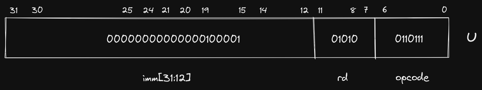
If we need to jump to or reference a farther away memory address, we have to
build up our constant via multiple instructions. This is where lui comes in.
The 20 bit immediate value in the U format instruction is placed in the upper
20 bits of the register specified in rd, which is a0 here. The lui
instruction is frequently coupled with addi, which allows us to then specify
the lower bits of that constant using binary addition before using it to access
that location in memory.
In fact, in our example, lui is coupled with addi to build up the memory
address of the format string that we pass to printf.
   0x00000000000100c8 <+24>:        lui         a0,0x21
   0x00000000000100cc <+28>:        addi        a0,a0,-192 # 0x20f40
   0x00000000000100d0 <+32>:        jal         ra,0x10418 <printf>
Let’s step through these instructions to observe what is happening:
(gdb) disass
Dump of assembler code for function main:
   0x00000000000100b0 <+0>: addi    sp,sp,-16
   0x00000000000100b4 <+4>: li  a1,2
   0x00000000000100b8 <+8>: li  a0,1
   0x00000000000100bc <+12>:    sd  ra,8(sp)
   0x00000000000100c0 <+16>:    jal ra,0x101b8 <sum>
   0x00000000000100c4 <+20>:    mv  a1,a0
=> 0x00000000000100c8 <+24>:    lui a0,0x21
   0x00000000000100cc <+28>:    addi    a0,a0,-192 # 0x20f40
   0x00000000000100d0 <+32>:    jal ra,0x10418 <printf>
   0x00000000000100d4 <+36>:    ld  ra,8(sp)
   0x00000000000100d8 <+40>:    li  a0,0
   0x00000000000100dc <+44>:    addi    sp,sp,16
   0x00000000000100e0 <+48>:    ret
End of assembler dump.
(gdb) i r a0
a0             0x3  3
At the start, the content of a0 is 3, which is the result from our sum
function. In binary this would look like: 00000000000000000000000000000011.
Now let’s step into the lui instruction and examine the contents:
(gdb) si
0x00000000000100cc in main ()
(gdb) i r a0
a0             0x21000  135168
After the lui instruction is executed, the upper 20 bits of a0 are populated
with the immediate value’s bits (0x21), and the lower 12 bits are filled in
with 0’s. In binary, our immediate was 00000000000000100001, and and adding
12 0’s to the end gives us 00000000000000100001000000000000 (or 0x2100).
Now let’s step into the addi instruction:
(gdb) si
0x00000000000100d0 in main ()
(gdb) i r a0
a0             0x20f40  134976
We can tell from the changed decimal representation that we have added -192 to
a0, but visualizing the binary addition helps us understand how lui and
addi are working together:
  00000000000000100001000000000000 (contents of a0 = 135168)
+ 11111111111111111111111101000000 (sign-extended immediate = -192)
----------------------------------
  00000000000000100000111101000000
Now we pass this value in our a0 argument register to printf, which points
to the address of the first character in our format string. We can examine the
contents of the memory address to be certain:
(gdb) x/15bc 0x20f40
0x20f40:    84 'T'  104 'h' 101 'e' 32 ' '  115 's' 117 'u' 109 'm' 32 ' '
0x20f48:    105 'i' 115 's' 58 ':'  32 ' '  37 '%'  100 'd' 10 '\n'
Like the S and B formats, U and J are also quite similar. The immediate
in J is scrambled in a similar manner to B because it is also used for
control flow instructions, which must use a memory address that is a multiple of
2. In our example, jal (“jump and link”) is our only J format instruction,
and is actually the only core instruction that uses the J format. Let’s
check out what it is doing:
(gdb) x/4bt 0x100c0
0x100c0 <main+16>:  11101111    00000000    10000000    00001111
Rearranged: 00001111 10000000 00000000 11101111
Fit into J format:
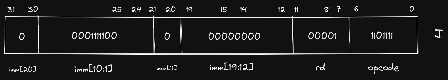
The jal instruction populates the register specified in rd (in this case
ra) with the memory address in the program counter (pc) register plus 4,
then jumps to the address by populating pc with the immediate value. In this
specific example, we are transferring control to the sum function, but making
sure that ra points to the instruction right after jal so that sum knows
where to return after completing its operations.
What is going on with mv and ret?
Link to heading
Before we conclude, I want to briefly touch on two instructions in our example
that we have not yet covered. You may have already noticed ret as it has no
operands, which would exclude it from all of the formats we have looked at.
mv, on the other hand, appears to use the R format, but actually is using
I.
These are both examples of pseudoinstructions, which are handy instructions
that make life easier for programmers, but are not specifically implemented in
hardware. Under the hood, our mv a1,a0 instruction is actually addi a1,a0,0,
which accomplishes a “move” of one register’s contents to another by adding 0.
Similarly, ret uses an instruction we didn’t cover in this post, jalr, which
behaves similar to jal, but uses a register and an offset rather than an
immediate value. ret is implemented as jalr x0,0(ra), which jumps to the
memory address in ra and essentially discards the link value as x0 is
hard-coded to 0 in RISC-V.
We see another optimization in RISC-V here with a register (
x0) that is hard-coded to0. We’ll explore more use cases for this functionality in a future post.
There are more pseudoinstructions that the assembler implements than these two,
some of which encompass multiple underlying instructions, but mv and ret are
ones that you will see often.
Concluding Thoughts Link to heading
This has been our longest post in the series so far, but it provides a strong grounding for future topics we will cover. Specifically, there are a number of design decisions that were only briefly mentioned or alluded to that we will explore in more depth. In addition, we will move beyond statements like “it makes the hardware implementation simpler” to actually showing how the logic is implemented.
As always, these posts are meant to serve as a useful resource for folks who are interested in learning more about RISC-V and low-level software in general. If I can do a better job of reaching that goal, or you have any questions or comments, please feel free to send me a message @hasheddan on Twitter!