This post is the first in a RISC-V Bytes subseries on the PINE64 Pinecil soldering iron and development board. Subsequent posts can be found under the RISC-V Bytes category.
I’ve been using the Pinecil as my primary soldering iron for a few months now. The neat thing about the Pinecil is that it is not only a highly portable USB-C powered iron, but it is also an interesting RISC-V development board. In fact, the Pinecil wiki lists this as an explicit goal.
Other irons only care if they can solder. The Pinecil is held to an additional standard; how well can it meet the needs of the open source community as a RISC-V development tool. It includes hardware features not found on other soldering irons such as BLE Bluetooth in the V2 in order to support FOSS community feature requests for both fun and science.
On top of this, the Pinecil also runs open source IronOS making it straightforward to modify and update its firmware. We’ll have plenty of fun with that in future posts, but step one in using the Pinecil as a development board is assembling the breakout board, which provides access to JTAG, ADC/DAC, I2C, UART, and SPI on the board.
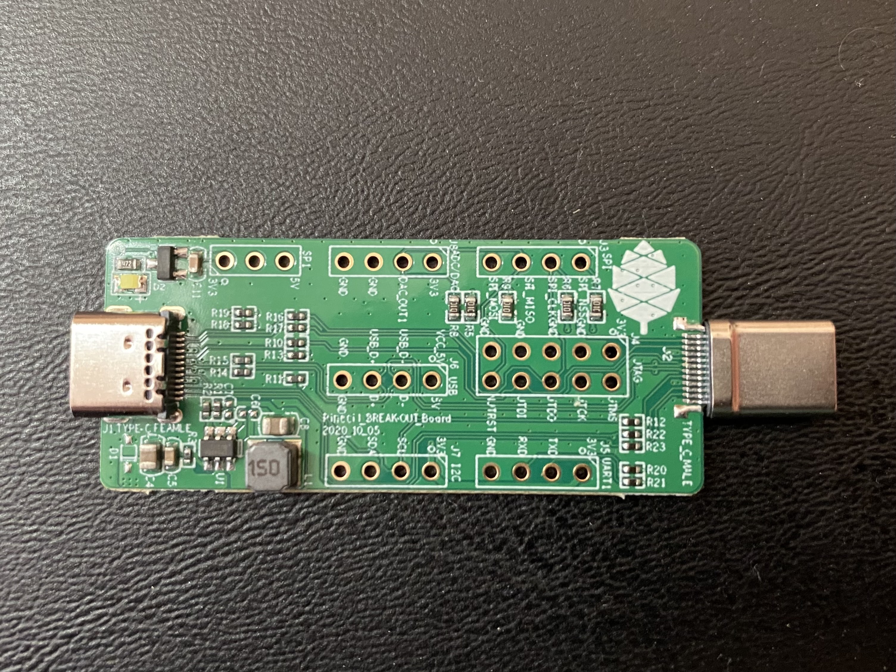
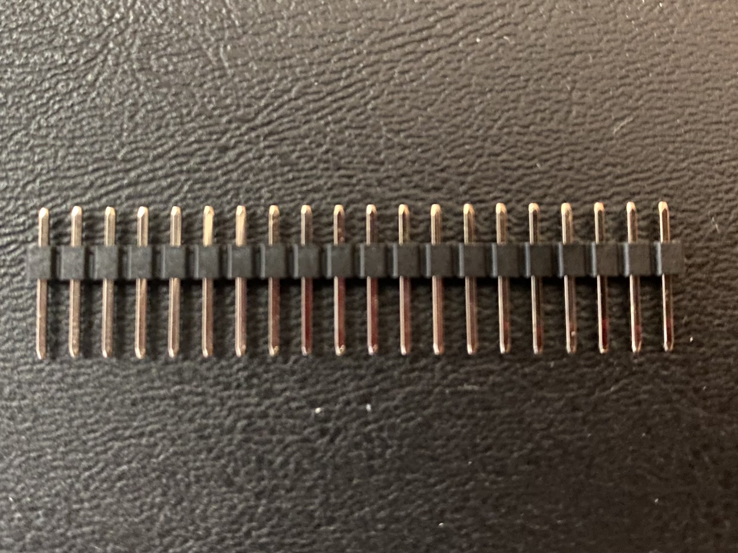
The board comes with a single-row male header pin strip (20x1), as well as a double-row male 10-pin header strip (5x2). The 10-pin strip is for the JTAG breakout, while the single-row strip can be broken up into five groups of 4-pin headers for the remaining protocol breakouts.
If you have a breadboard available, you can stick the long ends of the male pins into the breadboard, then place the breakout board on top with the short ends sticking through. The through-holes in the breakout board are nicely aligned such that the vertical distance between each group is one row.
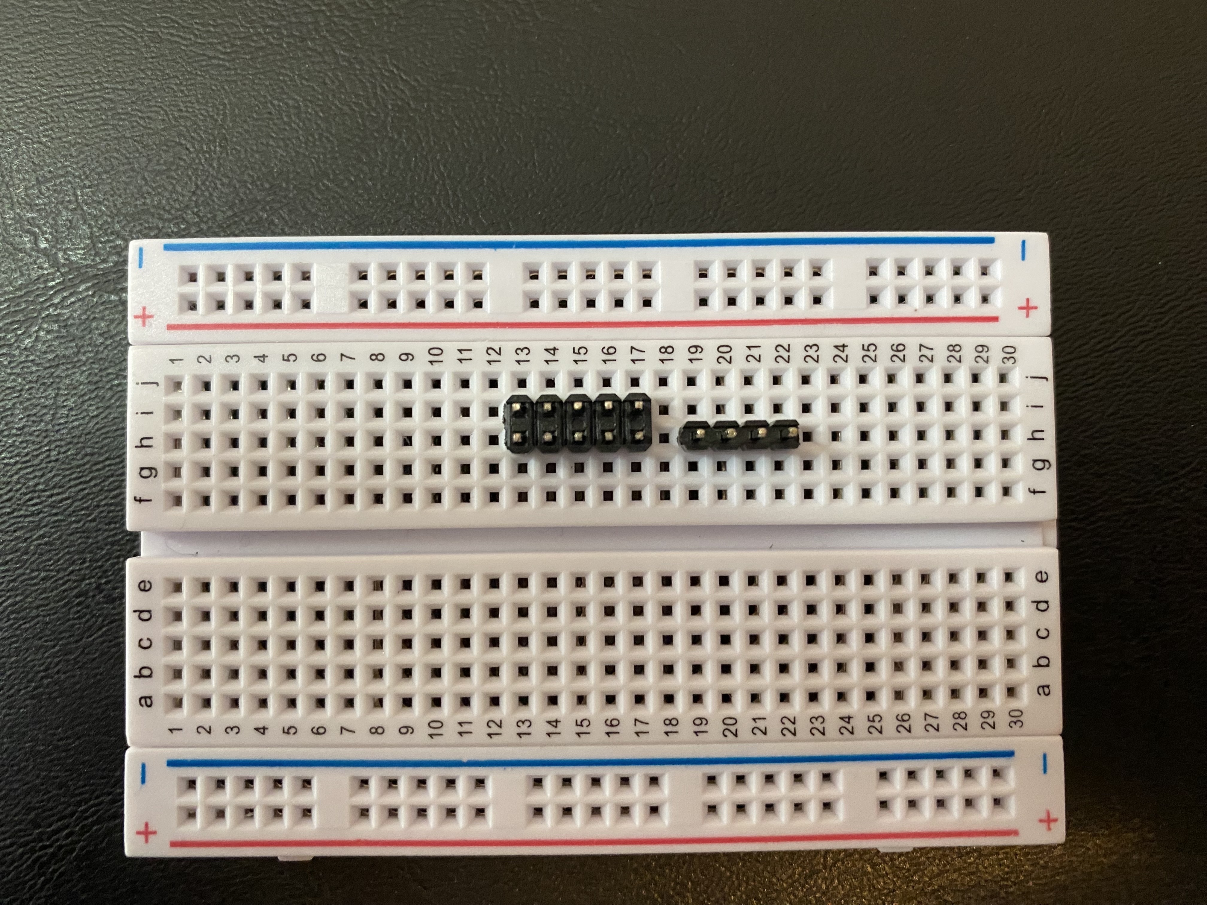
I started with just two groups of header pins, but placing them all before beginning soldering will allow you to avoid having to pull the breakout board out of the breadboard before you are done with all header pins. To solder through-hole header pins, touch the tip of your iron to one side of the pad, then apply solder to the other side of the pad. The solder should flow around the pad, resulting in a strong joint.
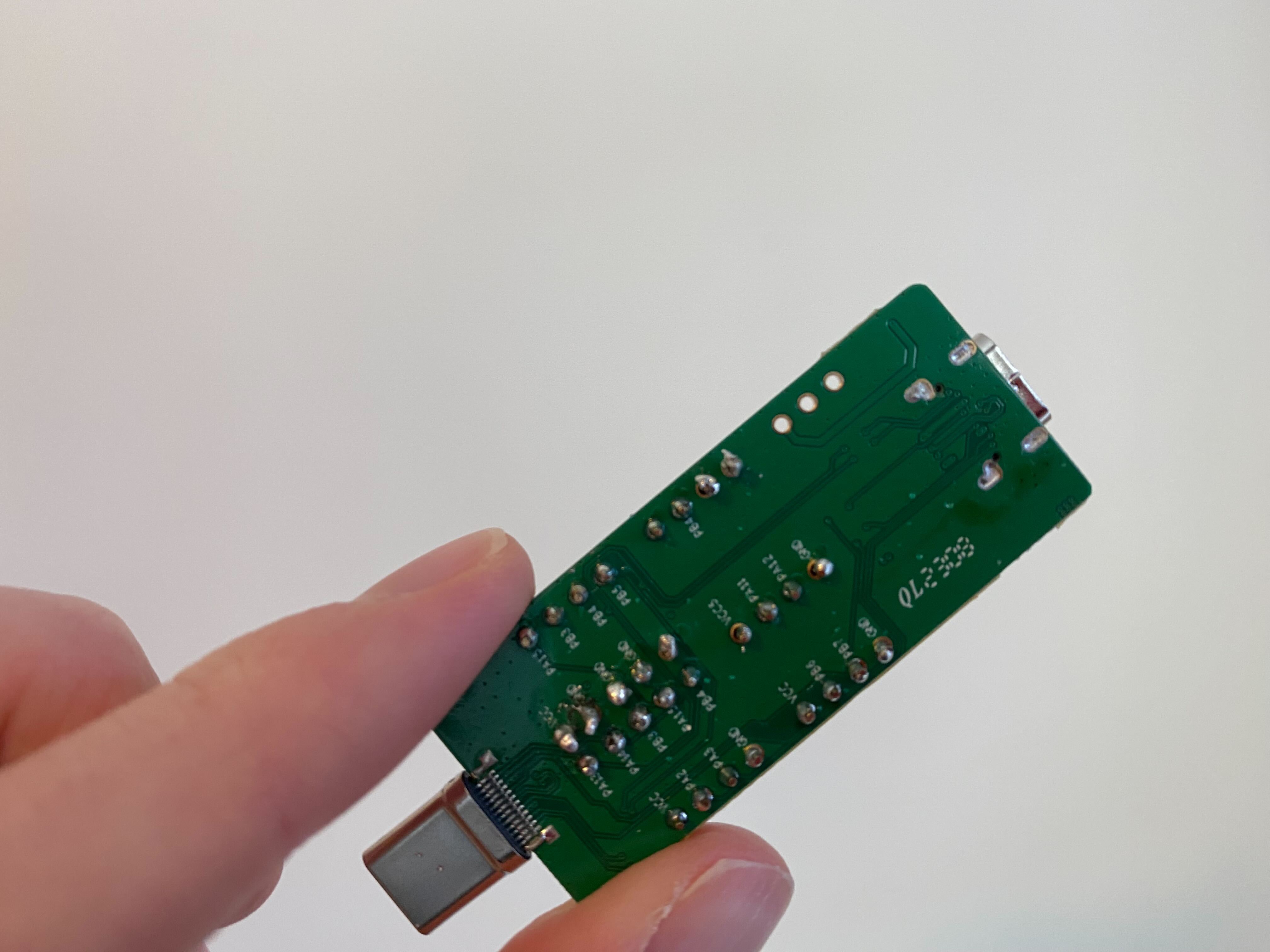
This was not my finest soldering work, but it got the job done.
With the header pins in place, we are ready to start using the Pinecil as a development board. In our next post, we’ll see how we can connect to the breakout board to start interacting with the RISC-V microcontroller.