The ESP32-S3 is a popular microcontroller (MCU) for a variety of reasons, such as its support for external pseudostatic RAM (PSRAM). One of its lesser known features is its Universal Serial Bus (USB) On-The-Go (OTG) controller.
The previously released ESP32-S2, as well as the new ESP32-P4, also have USB OTG support, with the latter having two controllers.
USB OTG devices can act as a device or as a host. This is a popular feature for smartphones, which, when attached to a laptop or desktop should act as a device, but may want to act as a host for some peripherals, such as a keyboard, that may be attached to it. The same can be true for a microcontroller, which may be programmed or debugged as a USB device, but may want to act as a host during normal operation.
Espressif’s esp-idf includes a USB Host Library, which can configure the USB controller to act as an OTG host, then exposes operations via higher level APIs. Though Espressif doesn’t document it anywhere, looking through the USB device and host driver implementations reveals that the ESP32-S3 uses the popular Synopsys DesignWare Core (DWC2) USB 2.0 OTG Controller, which is also used by STM32 MCUs and many others. Most of the configuration of the controller has to be reverse engineered because Synopsys does not publish documentation on its cores, nor does it allow for manufacturers to do so. The ESP32-S3 Technical Reference Manual only says the following in USB OTG controller register documentation (section 32.5):
The catalog and comprehensive specifications of USB OTG registers are subject to a Non-Disclosure Agreement (NDA) as mandated by the IP provider.
The USB host stack is composed of the following layers, which ultimately are accessed via abstractions offered by the Host Library.
- USB PHY
- USB Host Controller Driver (HCD)
- USB Host Driver (USBH)
- USB Enumeration Driver
- USB Hub Driver
These layers are configured on a call to
usb_host_install().
While there are a number of steps required for configuration, the most pertitent
to enabling OTG host functionality is setting the proper signals in the USB PHY.
In
usb_phy_new(),
the call to
usb_phy_otg_set_mode()
configures the PHY in host or device mode by connecting the proper peripheral
signals to logical 0 (GPIO_MATRIX_CONST_ZERO_INPUT) or 1
(GPIO_MATRIX_CONST_ONE_INPUT).
    if (mode == USB_OTG_MODE_HOST) {
        esp_rom_gpio_connect_in_signal(GPIO_MATRIX_CONST_ZERO_INPUT, USB_OTG_IDDIG_IN_IDX, false);     // connected connector is A side
        esp_rom_gpio_connect_in_signal(GPIO_MATRIX_CONST_ZERO_INPUT, USB_SRP_BVALID_IN_IDX, false);
        esp_rom_gpio_connect_in_signal(GPIO_MATRIX_CONST_ONE_INPUT, USB_OTG_VBUSVALID_IN_IDX, false);  // receiving a valid Vbus from host
        esp_rom_gpio_connect_in_signal(GPIO_MATRIX_CONST_ONE_INPUT, USB_OTG_AVALID_IN_IDX, false);     // HIGH to force USB host mode
        if (handle->target == USB_PHY_TARGET_INT) {
            // Configure pull resistors for host
            usb_wrap_pull_override_vals_t vals = {
                .dp_pu = false,
                .dm_pu = false,
                .dp_pd = true,
                .dm_pd = true,
            };
            usb_wrap_hal_phy_enable_pull_override(&handle->wrap_hal, &vals);
        }
    } else if (mode == USB_OTG_MODE_DEVICE) {
        esp_rom_gpio_connect_in_signal(GPIO_MATRIX_CONST_ONE_INPUT, USB_OTG_IDDIG_IN_IDX, false);      // connected connector is mini-B side
        esp_rom_gpio_connect_in_signal(GPIO_MATRIX_CONST_ONE_INPUT, USB_SRP_BVALID_IN_IDX, false);     // HIGH to force USB device mode
        esp_rom_gpio_connect_in_signal(GPIO_MATRIX_CONST_ONE_INPUT, USB_OTG_VBUSVALID_IN_IDX, false);  // receiving a valid Vbus from device
        esp_rom_gpio_connect_in_signal(GPIO_MATRIX_CONST_ZERO_INPUT, USB_OTG_AVALID_IN_IDX, false);
    }
After installation of the host library,
usb_host_lib_handle_events()
must be called in a loop to process USB host administrative events. Actual
interaction with devices is handled by
clients,
which are registered by calling
usb_host_client_register().
The esp-usb project includes a number
of client
implementations
(i.e. “device class drivers”) for different device classes, but there is also a
helpful
example
of installing a custom client, which only prints device information.
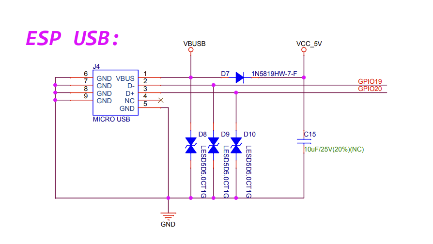
In order to run this example, we need to be able to connect devices to an ESP32-S3’s USB OTG peripheral. The ESP32-S3’s USB data lines are connected to fixed GPIO pins 19 (D-) and 20 (D+). Fortunately, on the ESP32-S3-DevKitC-1, these pins are wired to an onboard Micro-USB connector.

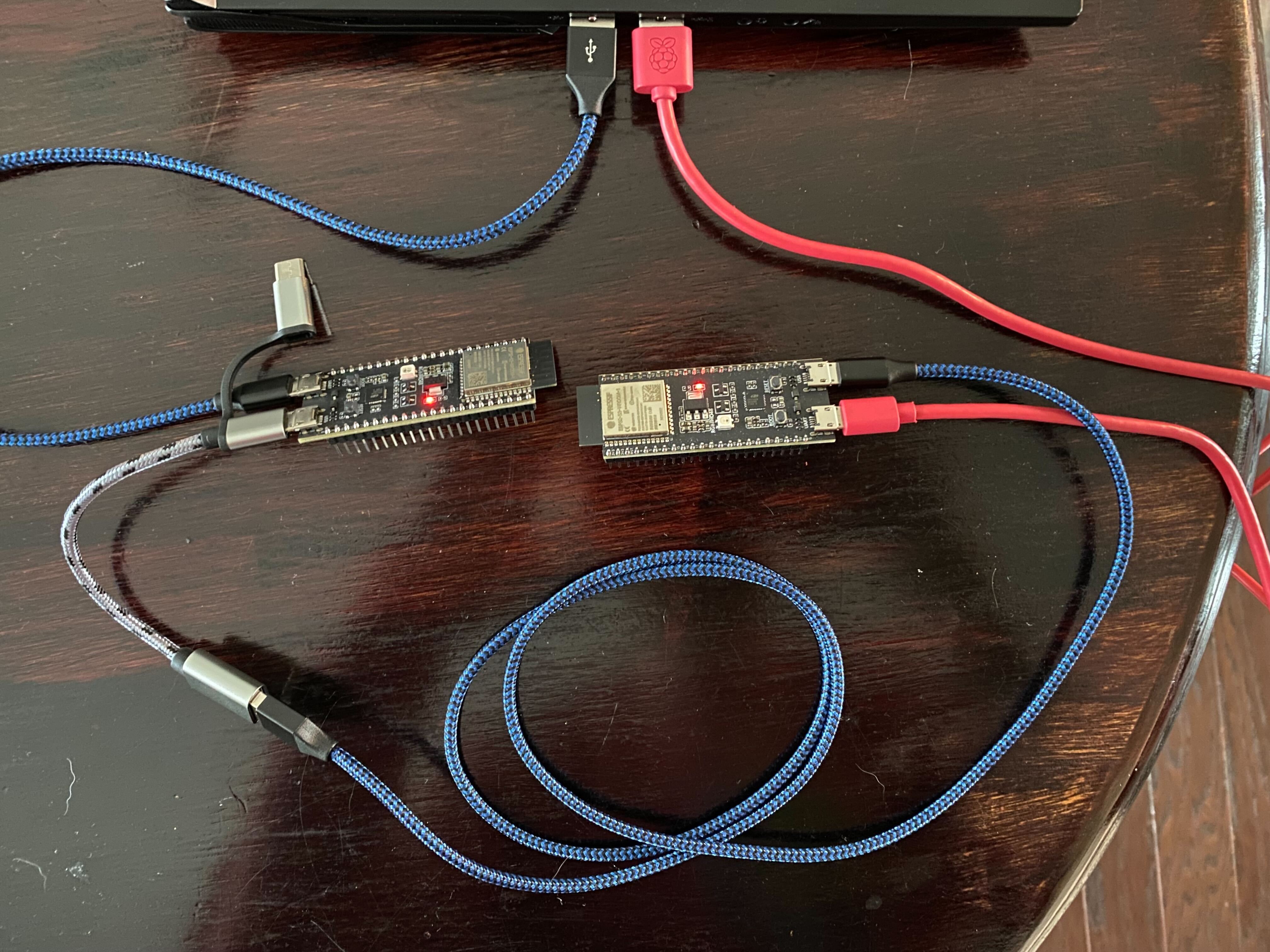
However, to connect a USB device to the DevKitC, we’ll need an OTG cable, such as a Micro-USB to Micro-USB, or an OTG adapter. I purchased a small adapter from Amazon that has a nice feature of supporting Micro-USB to USB-A or USB-C to USB-A. Because the DevKitC also includes a Silicon Labs CP210x USB-to-UART bridge that is accessible via a separate Micro-USB port, we can power, program, and monitor the output of the ESP32-S3 while its USB peripheral is connected to another device.
I happened to have a second DevKitC on hand, which served as a useful target because it could also be powered, programmed, and monitored via its UART-to-USB port, while being connected as a device to the first DevKitC via its USB peripheral port. The full setup looks as follows, with the device on the left serving as a USB OTG host, and the device on the right running a simple hello world program and serving as a USB OTG device.

| ESP32-S3-DevKitC | USB-to-UART Port | USB OTG Port |
|---|---|---|
| OTG Host | Connected to Laptop | Connected to OTG Device via Adapter |
| OTG Device | Connected to Laptop | Connected to OTG Host via Adapter |
With both kits connected to a laptop as serial devices, we can monitor the
output of each (Host: ttyUSB0, Device: ttyUSB1).
$ idf.py -p /dev/ttyUSB0 monitor
I (296) main_task: Started on CPU0
I (306) main_task: Calling app_main()
I (306) USB host library example
I (306) Installing USB Host Library
I (346) Registering Client
...
$ idf.py -p /dev/ttyUSB1 monitor
I (295) main_task: Started on CPU0
I (315) main_task: Calling app_main()
Hello world!
This is esp32s3 chip with 2 CPU core(s), WiFi/BLE, silicon revision v0.1, 2MB external flash
Minimum free heap size: 389836 bytes
Restarting in 10 seconds...
Restarting in 9 seconds...
Restarting in 8 seconds...
Restarting in 7 seconds...
Restarting in 6 seconds...
Restarting in 5 seconds...
Restarting in 4 seconds...
Restarting in 3 seconds...
After registering the custom USB Host Library client on the first DevKitC, we can see that it is able to successfully fetch device, configuration, interface, and endpoint descriptors, as well as string descriptors for manufacturer, product, and serial number, from the second DevKitC.
...
I (726) Opening device at address 1
I (726) Getting device information
I (726) 	Full speed
I (726) 	bConfigurationValue 1
I (726) Getting device descriptor
*** Device descriptor ***
bLength 18
bDescriptorType 1
bcdUSB 2.00
bDeviceClass 0xef
bDeviceSubClass 0x2
bDeviceProtocol 0x1
bMaxPacketSize0 64
idVendor 0x303a
idProduct 0x1001
bcdDevice 1.00
iManufacturer 1
iProduct 2
iSerialNumber 3
bNumConfigurations 1
I (756) Getting config descriptor
*** Configuration descriptor ***
bLength 9
bDescriptorType 2
wTotalLength 98
bNumInterfaces 3
bConfigurationValue 1
iConfiguration 0
bmAttributes 0xc0
bMaxPower 500mA
*** Interface Association Descriptor ***
bLength 8
bDescriptorType 11
bFirstInterface 0
bInterfaceCount 2
bFunctionClass 0x2
bFunctionSubClass 0x2
bFunctionProtocol 0x0
iFunction 0
	*** Interface descriptor ***
	bLength 9
	bDescriptorType 4
	bInterfaceNumber 0
	bAlternateSetting 0
	bNumEndpoints 1
	bInterfaceClass 0x2
	bInterfaceSubClass 0x2
	bInterfaceProtocol 0x0
	iInterface 0
		*** Endpoint descriptor ***
		bLength 7
		bDescriptorType 5
		bEndpointAddress 0x82	EP 2 IN
		bmAttributes 0x3	INT
		wMaxPacketSize 64
		bInterval 1
	*** Interface descriptor ***
	bLength 9
	bDescriptorType 4
	bInterfaceNumber 1
	bAlternateSetting 0
	bNumEndpoints 2
	bInterfaceClass 0xa
	bInterfaceSubClass 0x2
	bInterfaceProtocol 0x0
	iInterface 0
		*** Endpoint descriptor ***
		bLength 7
		bDescriptorType 5
		bEndpointAddress 0x1	EP 1 OUT
		bmAttributes 0x2	BULK
		wMaxPacketSize 64
		bInterval 1
		*** Endpoint descriptor ***
		bLength 7
		bDescriptorType 5
		bEndpointAddress 0x81	EP 1 IN
		bmAttributes 0x2	BULK
		wMaxPacketSize 64
		bInterval 1
	*** Interface descriptor ***
	bLength 9
	bDescriptorType 4
	bInterfaceNumber 2
	bAlternateSetting 0
	bNumEndpoints 2
	bInterfaceClass 0xff
	bInterfaceSubClass 0xff
	bInterfaceProtocol 0x1
	iInterface 0
		*** Endpoint descriptor ***
		bLength 7
		bDescriptorType 5
		bEndpointAddress 0x2	EP 2 OUT
		bmAttributes 0x2	BULK
		wMaxPacketSize 64
		bInterval 1
		*** Endpoint descriptor ***
		bLength 7
		bDescriptorType 5
		bEndpointAddress 0x83	EP 3 IN
		bmAttributes 0x2	BULK
		wMaxPacketSize 64
		bInterval 1
I (906) Getting Manufacturer string descriptor
Espressif
I (916) Getting Product string descriptor
USB JTAG/serial debug unit
I (926) Getting Serial Number string descriptor
68:B6:B3:4D:80:10
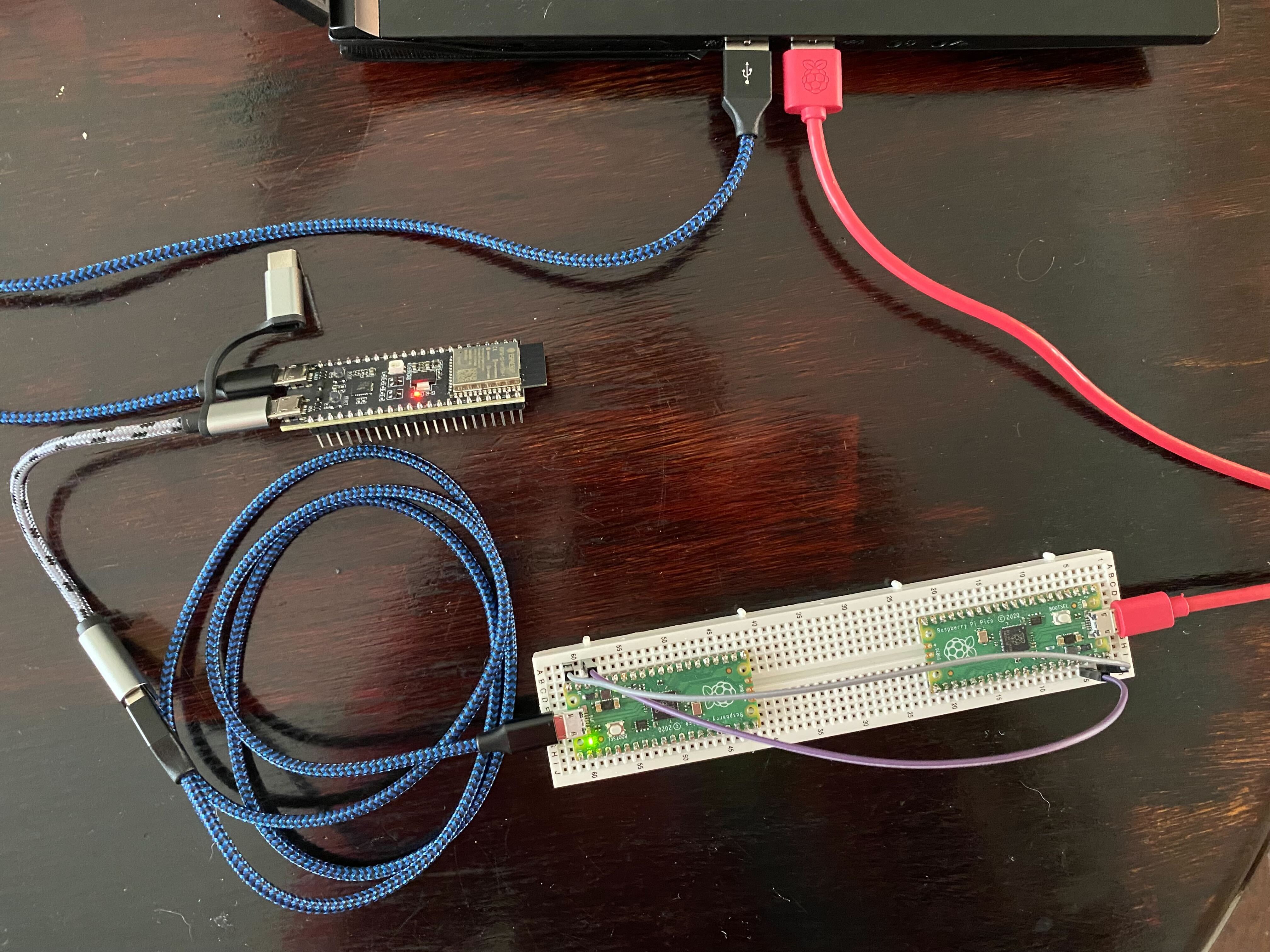
I wanted to test this out with some other devices, and being a big fan of Raspberry Pi’s MCUs, I always have a few Pico’s around the office. I still had one programmed with picoprobe from my post about accessing the Pinecil UART. I used a second Pico to power the first by connecting the second to the laptop, then connecting its VBUS (pin 40) and GND (pin 38) to the VBUS and GND on the first. I then connected the first to the OTG host DevKitC.

Sure enough, the USB Host Library client was able to fetch the same information
from the Pico, identifying it as a Picoprobe (CMSIS-DAP).
I (284686) Opening device at address 1
I (284686) Getting device information
I (284686) 	Full speed
I (284686) 	bConfigurationValue 1
I (284686) Getting device descriptor
*** Device descriptor ***
bLength 18
bDescriptorType 1
bcdUSB 2.10
bDeviceClass 0x0
bDeviceSubClass 0x0
bDeviceProtocol 0x0
bMaxPacketSize0 64
idVendor 0x2e8a
idProduct 0xc
bcdDevice 1.00
iManufacturer 1
iProduct 2
iSerialNumber 3
bNumConfigurations 1
I (284716) prusb: Getting config descriptor
*** Configuration descriptor ***
bLength 9
bDescriptorType 2
wTotalLength 98
bNumInterfaces 3
bConfigurationValue 1
iConfiguration 0
bmAttributes 0x80
bMaxPower 100mA
	*** Interface descriptor ***
	bLength 9
	bDescriptorType 4
	bInterfaceNumber 0
	bAlternateSetting 0
	bNumEndpoints 2
	bInterfaceClass 0xff
	bInterfaceSubClass 0x0
	bInterfaceProtocol 0x0
	iInterface 5
		*** Endpoint descriptor ***
		bLength 7
		bDescriptorType 5
		bEndpointAddress 0x4	EP 4 OUT
		bmAttributes 0x2	BULK
		wMaxPacketSize 64
		bInterval 0
		*** Endpoint descriptor ***
		bLength 7
		bDescriptorType 5
		bEndpointAddress 0x85	EP 5 IN
		bmAttributes 0x2	BULK
		wMaxPacketSize 64
		bInterval 0
*** Interface Association Descriptor ***
bLength 8
bDescriptorType 11
bFirstInterface 1
bInterfaceCount 2
bFunctionClass 0x2
bFunctionSubClass 0x2
bFunctionProtocol 0x0
iFunction 0
	*** Interface descriptor ***
	bLength 9
	bDescriptorType 4
	bInterfaceNumber 1
	bAlternateSetting 0
	bNumEndpoints 1
	bInterfaceClass 0x2
	bInterfaceSubClass 0x2
	bInterfaceProtocol 0x0
	iInterface 6
		*** Endpoint descriptor ***
		bLength 7
		bDescriptorType 5
		bEndpointAddress 0x81	EP 1 IN
		bmAttributes 0x3	INT
		wMaxPacketSize 64
		bInterval 16
	*** Interface descriptor ***
	bLength 9
	bDescriptorType 4
	bInterfaceNumber 2
	bAlternateSetting 0
	bNumEndpoints 2
	bInterfaceClass 0xa
	bInterfaceSubClass 0x0
	bInterfaceProtocol 0x0
	iInterface 0
		*** Endpoint descriptor ***
		bLength 7
		bDescriptorType 5
		bEndpointAddress 0x2	EP 2 OUT
		bmAttributes 0x2	BULK
		wMaxPacketSize 64
		bInterval 0
		*** Endpoint descriptor ***
		bLength 7
		bDescriptorType 5
		bEndpointAddress 0x83	EP 3 IN
		bmAttributes 0x2	BULK
		wMaxPacketSize 64
		bInterval 0
I (284866) Getting Manufacturer string descriptor
Raspberry Pi
I (284876) Getting Product string descriptor
Picoprobe (CMSIS-DAP)$
I (284886) Getting Serial Number string descriptor
E6616407E39D5B22
Using a microcontroller to obtain information about USB devices is interesting, but there is much more that can be accomplished when we go beyond simple control transfers. In future posts, we’ll dive deeper into the USB hardware and software stack, and examine what capabilities are offered by different types of devices.